
The next subject to be discussed in capacitance and the devices, capacitors. While resistors resisted the flow of electricity, capacitors actually store electrical energy, usually for very short periods of time. There are however, devices called super capacitors, that can store large voltages (but tiny current) much like batteries. They are very useful for powering circuits that may lose their primary power but can continue with voltage and low current, like CMOS circuitry which we will address later. Like resistors, capacitors come in a wide variety of types, values, accuracy tolerance, voltage, and current carrying capacities. When selecting a capacitor for use in a circuit, all of these must characteristics come into consideration, otherwise the circuit might not work, or worse, may be destroyed.
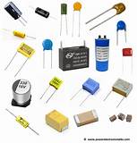
The figure below illustrates a few different types of capacitors. The capacitor may be made of air (separated by conducting metal plates), ceramic, plastic, glass, oil, tantalum, and probably more that I haven’t mentioned. Each material has different characteristics of determining capacitance and find preferred use in particular applications.
While the unit of measurement of the amount resistance is the ohm (Ω), the Farad is the unit of measurement of capacitance. A Farad is actually a huge amount of capacitance, most often we use millionth, billionth, or less values in circuits. A millionth (10-6) of a Farad is a microfarad (designated by µF or uF), a billionth is a nanofarad (nF or 10-9) while a trillionth is a pF or picofarad (10-12).
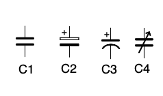
In the figure below, we can see several types of symbols that represent capacitors, C1 shows a non-polarized capacitor, typically made of ceramic, or plastic film. They are typically used to bypass noise to ground in power leads to semiconductors or power supplies, and in tuned circuits to perform timing or resonance when combined with a coil or resistor. C2 shows the symbol for a polarized capacitor which must be installed in a circuit with its + lead attached to a more positive lead and the other lead attached to a less positive component or lead. Failure to observe the correct polarity can result in the explosion of the capacitor. C3 is the more modern symbol for a polarized capacitor. C4 is a symbol of a variable capacitor, typically used in a tuned circuit to achieve resonance of the circuit over a range of frequencies. Variable capacitors are attached to the tuning dial of a radio to allow you to select the station you want to hear. Variable tuning capacitors typically use air as the non-conductive dielectric portion of the capacitor.
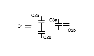
Capacitors can be arranged in either stand alone, series, or parallel configurations. However, the total capacitance exhibited by the combination is much different than when resistors are combined. Capacitors C2a and C2b in the figure below are series connected while C3a and C3b are parallel connected. Series connected capacitors add their values like parallel resistors. To compute the value of the combination of C2a and C2b, you would add 1/C2a and 1/C2b and then take the reciprocal of that total C = 1/(1/C2a)+(1/C2B). The value of parallel connected capacitors is C = C3a+C3b sort of like the combination of series connected resistors.
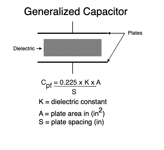
Below we have a diagram of a generalized capacitor. It is composed of two or more conductive plates separated by a dielectric material which may be only partially conductive. For instance, a non-conductive vacuum has a dielectric constant of 1.0 while air is 1.0006 and ceramic is 3-7. We see that the capacitance (in picofarads pF) can be roughly determined the area of the conductive plates multiplied by the dielectric constant of material between the plates all divided by the spacing between the plates. As the spacing increases, the capacitance decreases. As the dielectric constant or plate area increases, the capacitance increases.
Now, let’s use a capacitor in a simple circuit containing a battery, a single pole switch, a resistor, and a capacitor. the instant the switch is closed, current starts to flow from the battery into the resistor and is limited by the resistor, and then into the capacitor. As shown in the grayed portion of the graph, voltage and current instantly goes from 0 to the maximum that can be supplied by the battery, then begins to decrease as the capacitor begins to charge then reach the full charge of the battery limited by the resistor (shown by the dashed line of the graph). At the point t on the Y time axis, voltage reaches maximum, and current minimum – the capacitor is fully charged. The time t that it takes to reach that point is called “time constant” and is computed by t = RC where R is the resistance in ohms (Ω) of the resistor and C is the capacitance measured in Farads of the capacitor.. If R = 1000Ω and C = .000001F or 1 uF or μF, t = 1000x.000001 = 0.001s or 1 millisecond.
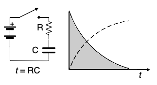
Time constants are widely used in electronics, you will run into it many times. It is used to determine the frequency of oscillators, the timing of pulses, the resonant frequency of filters, many, many places.
The flow of current (electrons) through a capacitor is dependent upon both the frequency of the alternating signal and the value of the capacitance. The greater the capacitance, the more electrons are required to bring the capacitor to fully charge to the source-voltage value. It is possible, in an AC circuit, to control the current flow by changing the capacitance just as a resistor controls the flow of current. The AC resistance effect is called capacitive reactance measured in ohms. Reactance is termed X while capacitive reactance is shown as Xc. The full formula is: Xc = 1/2πfC. We will encounter a different type of reactance again when we talk about inductors or coils. The higher the frequency or the higher the capacitance, the lower the total reactance because the formula is a reciprocal (divided by 1).
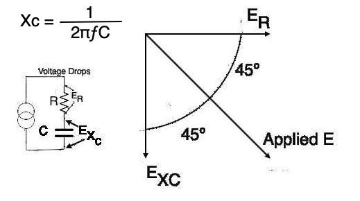
As we saw in the graph in the time constant illustration, it takes a finite amount of time for the capacitor to charge to the maximum amount of applied voltage. Similarly, it takes an amount of time for the capacitor to discharge once the applied voltage is removed. This delay in charging and discharging causes a phase shift from the original applied signal. Again, referring to the graph, we see that the applied current instantly reached maximum but then tapered off as time progressed. Conversely, we saw that the applied voltage took some time to increase to its maximum level. So voltage lags current, or current leads voltage by some amount of delay. In a purely capacitive circuit (no resistance) that voltage delay will be by 90º, decreasing to 45º as the circuit resistance approaches the value of capacitive reactance.
Capacitors are not perfect. They have some amount of intrinsic resistance in them dues to their leads and dielectric losses. This resistance contributes to the slight phase lag through the component and may be added to the external, much larger resistance. This intrinsic resistance is called ESR or equivalent series resistance. ESR is an AC measurable phenomenon, not DC, and increases with frequency. ESR is much lower in ceramic and plastic film capacitors, and much higher in electrolytic and tantalum capacitors. The much higher ESR in electrolytics can become a problem with age. The dielectric dries out with time and can raise the ESR to a point that it causes excessive internal heating of the capacitor and even catastrophic failure of the component.