
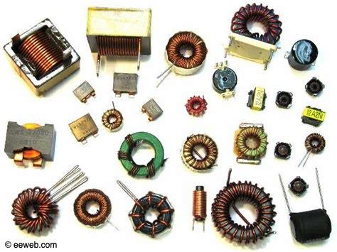
Another component that has a lot of variants is the inductor. Transformers are also a type of inductor that will be covered later in the Blog. Inductors are basically a coil of wire, however, that coil can be formed by many different techniques and wound around air, iron, ferrite, or plastic.
As we learned in the Magnetism section, when a DC voltage is applied to a wire, the wire radiates a magnetic field. When the wire was coiled around an iron core (such as a nail) a fairly strong magnetic field was created around the core and the nail acted as a magnet. Withdrawing the nail still left a magnetic field in place, though quite a bit weaker due to the removal of the highly permeable iron nail core.
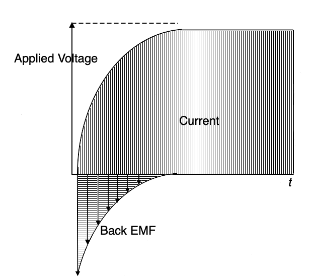
From the instant that current is applied to the wire or coil of wire, a magnetic field expands from the center of the conductor outward. As the magnetic field moves through the conductor, an opposing voltage is generated in the conductor (the same way that a conductor moving within a magnetic field creates voltage in a generator) in a direction that opposes the applied current. That generated voltage is called a “counter” EMF or “back” EMF. As the current comes to a steady state, the back EMF dissipates. That effect is shown in the diagram below. Although the effect is seen in straight conductors, the effect is greatly multiplied when the conductor is formed into a coil and still more when a conductive core is added to the center of the coil.
Recall from the section on capacitors that there is always a bit of a delay in the increase in charging voltage as current is applied (and a decrease in current flow as the maximum charge is reached). The main contributor to that delay was the series resistance (the R) in the time constant circuit, although ESR also contributed to the delay. Additionally, there is a slight amount of resistance in the wire in the coil that contributes to a similar effect in inductors as well.
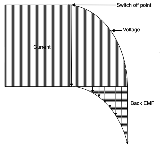
Now, just as when current begins flowing into an inductor it creates a back EMF due to the expanding magnetic field, when that current is removed, abruptly, like when a switch opens, the magnetic field collapses, and that movement of the field through the conductor again creates a back EMF. That may cause problems in a variety of circuits. In power grid circuits, that back EMF may cause spark jumps in distribution equipment potentially causing fires. It circuits carrying low voltage DC in relay contacts it may also cause sparking which could disrupt signals in adjacent circuitry. There are ways to mitigate these back EMF difficulties which will be discussed later. For now, be aware of the back EMF phenomenon that occurs as current is both applied and removed from an inductor.
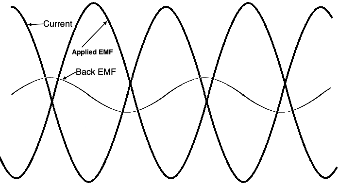
In the illustration above we can see an exaggerated representation of an AC signal and the much reduced back EMF signal generated in an inductor.
Any change of current amplitude or direction in a conductor causes a back EMF which opposes the change of current flow. DC does not create a back EMF but varying DC and AC do. Inductance then is defined as the property that opposes the change in current or is the energy that is stored in an electromotive field. Inductance is measured in Henrys and an inductor is indicated by the symbol L. A single Henry is a huge amount of inductance, and like Farads with capacitance, we usually deal with millihenrys (mH) or microhenrys (uH or µH). The ability to oppose changes in current can be exploited to help smooth out power in power supplies and RF frequency circuits. When designed for these uses, they are called chokes because they choke off changes.
The inductance of a coil increases as the number of turns squared (N2). If there are 2 terns, the inductance is multiplied by 4 over a straight wire., 3 turns multiplies the value by 9, and so on. However, if the coils are spread out, the inductance decreases so the length of the coil comes into play. Also as the radius or diameter of the coil increases, more wire will be used and inductance will increase. A formula then that approximates the inductance is given by: L(µH) = r2N2 / 9r+10l where r is the coil radius in inches, N is the number of turns, and l is the length in inches.
Like capacitors, inductors can be combined with resistors to make a circuit that has a time constant. T = L/R (T is the time in seconds, L is the inductance in Henrys, and R is in ohms.
Inductance values in series and parallel combinations are computed just like resistances. L = L1+L2+L3 for inductances in series, and L = 1 / 1/L1+1/L2+1/L3 for inductances in parallel.
Referring to the illustration above, as the current increases through an inductor, the magnetic field also increases. At the moment that the current reaches its maximum, the rate of change drops to zero. As the current decreases toward zero, the magnetic field collapses inward to the conductor reaching a maximum positive or negative peak at the zero current point. Current leads applied voltage by 180º while induced back EMF lags current by 90º.
We have seen that DC flowing in an inductor has no dynamic effect, however AC does. As the current increases and decreases (let’s consider a steady state AC wave to begin with), the induced back EMF voltage resists the change. This resistance to change is called reactance. Inductive reactance, indicated by the symbol X, is a measure of how much the back EMF opposes the current change and is measured in ohms. A 1H inductor will have a specific reactance in a 60 Hz circuit while a 2H inductor will have twice as much reactance in the same circuit. Therefore, reactance is directly proportional to the inductance. The equation XL = 2πƒL where ƒ is the frequency in Hz, L is inductance in Henrys. 2πƒ is used so many times in electronics it has its own special symbol, ω. So, XL = ωL.
Reactance fits into Ohm’s Law equations just like R. So E = IXL, XL = E/I, I = E/XL. Additionally, inductive reactance in series or parallel circuits is computed just like resistance: XL: = XL1+XL2+XL3 for series circuits; XL = 1/1/XL1+1/XL2+1/XL3 for parallel inductances.
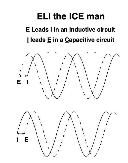
The illustration below shows E leading I in an inducative circuit while I leads E in a capacitive circuit. We can remember this difference with the nemonic “ELI the ICE man”. In all of the illustrations in the blog so far, we’ve had to represent the AC signal’s waveform as a steady state AC. In reality, that very rarely happens. Usually the AC signal is varying in amplitude . frequency, and phase at extremely high speeds making illustration impossible. For our purposes here, we are learning the basics, not trying to illustrate reality.
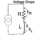
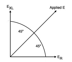
This next illustration shows an AC signal source along with a resistor (R), and an inductor (L). As we saw in the previous illustration, there are actually two voltages present in this circuit: (1) the applied signal voltage and (2) the back EMF voltage. The voltages are in different phase relationships with the applied current (since this is a series circuit, the current is the same through the components) – however, the applied voltage is 180º out of phase with the current while the back EMF is 90º out of phase with the applied current. Both voltages interact with the resistance. One voltage drop across the resistor is ER, the other voltage drop across the coil due to inductive reactance is EXL. For the purposes of this discussion, we will make the voltage drops equal, thus ER = EXL. So, here we have a vector phase diagram of a steady state AC signal (applied EMF) in a series L-R circuit with equal resistance and inductive reactance values. We see that the vector representing the inductive reactance is 90º behind the applied signal (the vertical vector) while the resistive vector is 90º ahead of the applied signal (the horizontal vector).
Why all of this attention to phase relationships? We will see how resistors, capacitors, and inductors are combined into circuits that perform a variety of critical functions such as: timing, oscillators, tuned circuits, and filters in later sections. Without those circuit elements, radio transmission, reception, television, telephone, and computing circuits would not be possible.