
This section will introduce you to the simplest of electronic components, the
resistor. There are many forms of resistors to suit the intended application.
If an EMF (electromotive force) or voltage can flow from one point to another,
the material it is flowing through is termed a conductor. If, on the other hand,
no EMF flows, the material is termed an insulator. The best conductor is gold,
next silver, then copper, and aluminum. The best insulator is glass and ceramic,
other insulators like rubber, plastic, and paper are used to isolate conductors.
As conductors increase in length, their resistance also increases.
Resistors are used to impede the flow of current or voltage, and to interact
with other components like capacitors and sometimes inductors to create turned
circuits.
Resistors come in a very wide variety of types and forms, from devices that
measure light and heat and sound, to devices that control audio loudness, to
devices that control light, heat, and power. Resistors can be made of lengths of
wire, carbon powder compressed into tubes, and metal foil, oxide, or vapor
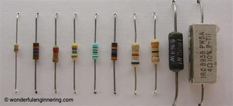
sintered onto insulating forms. Most often, when building electronic circuits, I use metal film resistors. They are daily temperature stable, lower noise generating than carbon, available is several power ratings and accuracies, and are low cost. Interestingly, it is difficult to predict the final resistance of a manufactured resistor so these days, the process is more one of a measuring and sorting operation. Manufactured resistors are measured then sorted into batches of similar devices that are all within 1%, 5%, or 10% of the intended value. Just a few are shown in the illustration below.
The values of resistors are measured in ohms. Resistors range in values from
1/1000th of an ohm to many millions of ohms. The most common values that you
will use and run into range from about .5 to 1,000,000Ω. The higher and
lower values are used for special purposes. Besides the value of resistance of
the component itself, you will need to know and consider its power value and
component accuracy. The most common power values are 1/4, 1/2, and 1 watt
values. Smaller and much larger power handling capability are also available.
The most common accuracy values are 1%, 5%,and 10% although much more precise accuracies are available for special purposes.
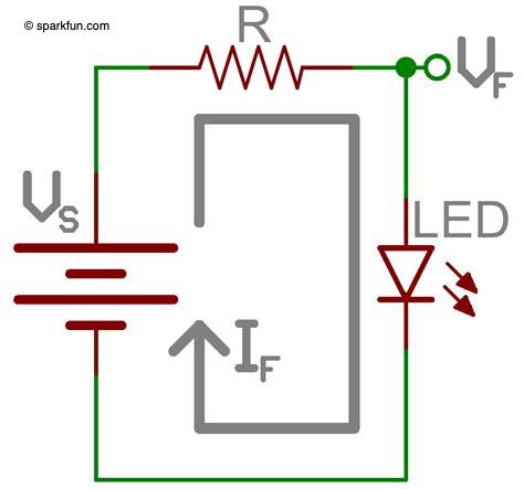
To determine the power value of the resistor you intend to use, you need to know
the ranges or voltage or current that will flow through the resistor, then use
the variants of Ohm’s Law to determine the power rating. For example, ass Ume
you need a resistor to limit the current flow to an LED in a circuit that has 12
volts available. The resistor’s value will need to be (12V – (1.2Vf of the LED –
the forward voltage drop across the LED) = 10.8V) x (.020 A for normal
brightness) = 10.8/0.020 = 540Ω. The nearest standard value, not exceeding
the required 0.02A of current) is 560Ω. Now, to determine the power rating
of the 560 ohm resistor we square the current and multiply by the resistance:
I2xR = .0004×560 = .224W which is a little too close to 1/4W so best to use 1/2W
power rating so it won’t overheat with the current flowing through it. See the
illustration below.
The ohmic value, accuracy, and power handling capability of most resistors can
be identified by a color code imprinted on the body of the component. The code
may be memorized by: BROYGBVGWB. Which stands for Brown, Red, Orange, Yellow, Green, Blue, Violet, Gray, White, Black; 1,2,3,4,5,6,7,8,9,0. A resistor with a
color code of Brown, Green , Yellow would have the digits 15 then the number of
zeros to add to the first two digits. The third ring of yellow indicates 4 zeros
to add to the resistor’s value so the final value would be 150,000. Similarly a
fourth ring indicates the accuracy tolerance: gold, 5%, silver, 10%. Power
handling is usually indicated by size: the smallest is usually 1/10W, next 1/4W,
then 1/2W, 1W, 5W, 10W, 50W. The larger resistors, usually larger than 1/2W,
will have the power value printed on the body of the component.
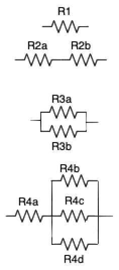
Several resistors are shown the the figure above. The symbol used on schematic
diagrams of a circuit is shown as R1. If two resistors are connected in series,
they are shown as R2a and R2b. Resistors connected in parallel are shown as R3a,
R3b, and R3c. Finally, if resistor combinations are connected in series and
parallel, they may be shown as R4a, R4b, R4c, and R4d. There can be many
combinations of all these types of connections.
When resistors are connected in series, as shown by R2a and R2b, the total
resistance of the combination is the sum of each of the individual resistors in
the network. For example, if Ra = 150 ohms, and Rb is 400 ohms, the series
combination is 150+400 = 550.
When resistors are connected in parallel such as R3a and R3b, the combined
network is a bit different: it is: 1 / 1 / R3a + 1 / R3b. If R3a = 100 ohms, and
R3B is 500 ohms, the parallel combination shown is 1 / .01 + .002 = 1/.012 =
83.33. If all the resistors connected in parallel are of the same value, you may
calculate the network as a special case as R1xR2/R1+R2. For example if R1=R2=100
ohms, the parallel combination of the two in parallel would be 100×100/200 = 50.
Voltage is a circuit is measured across one or more components, while current is
measured within a circuit. In the circuit below (part 1), we see that a
voltmeter is applied across the resistor network, which the ammeter is applied
within the circuit. Lets assume that the voltmeter reads 100V in this circuit
while one resistor has a value of 100 ohms, and the other has a value of 800
ohms. The parallel circuit of the two resistors (in part 1) is 1/1/100+1/800 =
88.88 ohms of resistance. When placed in a 100V circuit, by Ohm’s law, we see
that E/R = I and thus 1.125 amps of current would be shown by the ammeter A1.
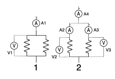
In the illustration’s part 2, we have added a couple more meters to see that the
voltage across the two resistors as measured by meters V2 and V3 both still read
100V, just as did V1 in part 1. However, we can see that “current divides” in
the two parallel resistors. A2, the ammeter in the 100 ohm resistor circuit will
read 1.0 amp while the ammeter A3 will read 0.125 amps.. A4, the ammeter reading
the current for the entire parallel resistor circuit will still read 1.125 amps.
We see that current divides in parallel circuits, voltage does not.
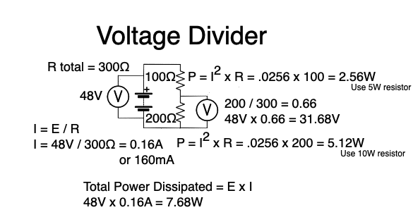
Now, let’s consider a commonly encountered circuit construct called a voltage
divider. A voltage divider is used to obtain a lower voltage from a higher
voltage. It is composed of resistor networks (either series or parallel
combinations or both) and a higher voltage source than you wish to obtain. The
voltage divider is shown in the illustration below.
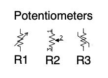
There are several other critical components that are based upon the simple resistor. One of the simplest is the potentiometer or pot, really a variable resistor. The devices have three terminals, two are just like a fixed resistor, the third is like the voltage takeoff terminal we saw in the voltage divider. Three different symbols for potentiometers are shown below. The center one, R2, illustrates the three terminals. Terminal 2 is the “take off” pin for the variable resistance between terminals 1 and 3. The fixed portion is between terminals 1 and 3, the variable resistance is between terminals 1 and 2, or 2 and 3, depending upon how you want the circuit to work. That variable resistance appearing at terminal 2 is usually determined by the rotary position of a control knob, or the vertical position of a slider. Varying the position of the knob or slider changes the resistance appearing at that variable terminal. There are many uses for such a device.
In addition to pots, variable resistors are used to detect changes in temperature (termed thermistors), light (termed photocells), or sound (termed electret microphones). There are probably others.
73… W3SEH