
The people – the physicists – we have encountered here all used experimental
procedures and activities to arrive at their conclusions (often wrong, of
course). They took notes of their findings, pondered the reasons why they were
observing actions and reactions, and then published and discussed their
observations and conjectures. We’ve already seen how clever some were. For
instance, the torsional balance used by Coulomb was extraordinary. To have been
able to measure, not absolutely but relatively, the tiny differences he noted in
the charges placed on materials that he then carefully moved about to determine
the inverse square of the distance relationship of charge repulsion was
extraordinarily beautiful work.
As use of Volta’s battery or versions of the pile became more popular, it was
possible to replicate and then extend the work of others because their results
and findings were repeatable so that knowledge could be verified and then
extended. The investigators noticed that their circuits and apparatus,
interconnected by various materials and mechanisms, often developed heat within
the assemblies. The German physicist Georg Ohm, in 1827 published his
observational findings concerning voltage, current, and lengths of wire. His
findings reported that readings from a galvanometer (a device which measures
current and invented by Hans Oersted in 1820) were directly proportional to the
length, diameter, and type of wire and the voltage applied to the circuit. Today
we know that relationship as I = E / R, R = V / I, and E = I x R[1]. This
equation, known as Ohm’s law, was agreed upon in 1861. It is extremely important
and needs to be committed to memory.
When I was a kid, I asked a fellow how I should go about learning electronics.
He said simply, “all you need to know about electronics is Ohm’s Law”.
Interestingly, he was right. It was not at all obvious, then, how that could be.
Ohm’s Law is so simple – just three terms. I was bored with it in five minutes.
Little did I know then!
The variation in voltage and current due to the length, type, and diameter of
wire came to be called the resistance to the flow of electronic charge. The
definition was set as a proportional relationship between voltage and current
and measured in units to be known as ohms. One ohm is defined to be the
resistance in a circuit passing one amp of current with a potential difference
of one volt. The value ohm is used so often in electronics that it has it’s own special symbol, the Greek letter omega, Ω The majority of electronics is devoted to this simple and
inseparable relationship. The manipulation, measurement, and response to these
three values: current, voltage, and resistance.
Resistance became quite useful for regulating the amount of voltage and current
in a circuit. Soon, devices termed resistors, made from various lengths and
diameters of wire became available to experimenters. Lengths of wire made from
different metals offered a wide variety of resistance values in many different
physical forms. It was discovered (and patented in 1905), that wire made from a
combination of iron, nickel, and chromium (to be called nichrome), offered both
very high resistance and very high heat tolerance. Nichrome wire became very
common for use in all types of heaters, most commonly, toasters. Carbon powder,
compressed into small cylinders, sorted into like values and labeled by their
value, became widely commercially available as devices known as resistors. There
are now a huge variety of resistors made from sputtered metal films, carbon
films, wire, ceramic, and conductive plastics. All have various characteristics
which are useful in all kinds of circumstances. Some resistors vary their value
of resistance based on other physical characteristics such as heat and light.
Heat dependent resistors are useful for varying the amount of current and
voltage in a circuit (which can be measure with a meter) based upon the
temperature that the resistor is being subjected to – a thermistor. Photocells
are light dependent resistors useful for measuring either the amount of light
present, or just the presence or absence of light. When used to detect the
presence of light, a photocell can be used to trigger door openers, turn on
lights when it becomes dark, or count items interrupting a beam to make sure the
right number of candy bars fill a box. Various forms of resistors are all around
us performing useful functions.
The relationship between voltage (E), current (I), and resistance (R) can be
represented by the simple figure below.
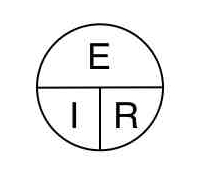
E, the symbol for voltage is placed over the I, symbol for current and R, symbol
for resistance. You can remember then that to find the voltage value E, you can
cover it with your finger which will then leave the I and R side by side,
meaning to multiply them together – you need to multiply current by resistance.
In a similar manner, to find out the current, cover the I with your finger
leaving the E to be divided by R. To find the resistance when given the voltage
and current, cover the R and see that you need to divide the voltage E, by the
current I. Hopefully, you can remember this representation of the three values
and their orientation, then be able to recall how to find the needed value given
the other the other two.
[1] E = voltage, I = current, R = resistance
73…W3SEH